For designers and engineers, the ability to seamlessly combine drone data with their existing CAD capabilities has meant faster, more efficient workflows. Planning earthwork for land development and roadway design projects, developing community masterplans, and performing material takeoffs has been made easier thanks to advances in drone surveying software.
Autodesk Civil 3D is a common CAD software used for civil infrastructure design and documentation—and one that’s particularly easy to use alongside drone data platforms. Below, we walk through the five most common Civil 3D workflows that you need to know if you’re going to integrate drone data into your CAD work.
1. How to import an orthophoto into Civil 3D (JPEG and GeoTIFF)
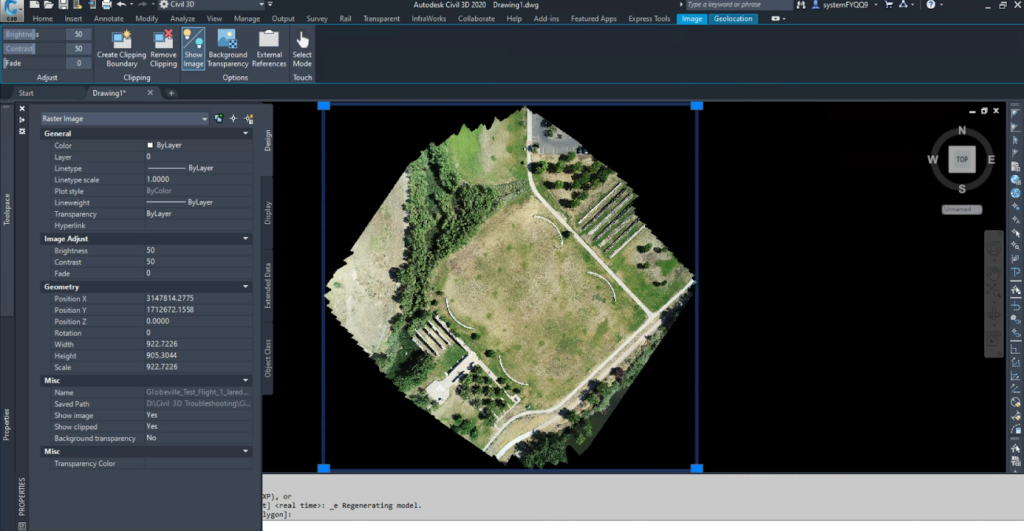
Orthophotos are 2D aerial images that have been created by stitching together hundreds of individual drone photos and rectifying for angle and distortion. Orthophotos in DWG files are frequently used by engineers and land developers to generate planning documents, such as masterplans, subdivision phasing plans, and zoning exhibits.
They also aid in development of civil designs for a variety of projects. A model can be loaded on top of an orthophoto in Civil 3D. Here’s how to upload an orthophoto:
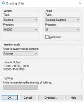
- To avoid issues with the orthophoto scaling, you’ll want to keep the Insertion units at the default of Unitless. To confirm this, enter the command “units” to pull up the Drawing Units dialog box.
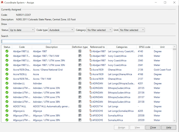
- Select your desired coordinate system. Type the command “mapcsassign” to pull up the Assign dialog box. There, enter your coordinate system’s EPSG code and assign your desired coordinate system.
- Type the command “mapiinsert” to upload your file. If you’re uploading a .TIFF, uncheck the Modify Correlation box. Since the orthophoto is already georeferenced, transformations or modifications to the insertion of the image are not necessary.
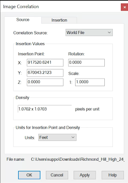
If uploading a JPEG, two additional files will be downloaded: a WLD and JGW. These need to remain in the same folder as the JPEG to enable Civil 3D to correctly insert the orthophoto. To make sure Civil 3D is able to read the WLD file, check the Modify Correlation. This will pull up the Image Correlation when you upload your file, where you can verify that the Correlation Source is set to World File.
- To zoom to the extents of the image, type the command “ze.” The insertion coordinates can be viewed by selecting the orthophoto and opening the Properties pane or by selecting the orthophoto and entering the command “MO”.
5. Save your drawing.
2. How to export a TIN Surface DWG to a DXF
Instead of exporting survey data to use in Civil 3D, you might choose to take the opposite approach: importing design files and final grade surfaces to a drone data platform.
The advantage of this is that you only have to upload those design files once (until inevitably your design changes). As you add more surveys to your drone software over time, you can then measure your progress against those designs.
Because .DWG files are interoperable with few non-CAD programs, you’ll need to convert your design files into DXFs before you can export them from Civil 3D.
- Open the existing DWG containing the TIN surface. The drawing should already be georeferenced in the proper coordinate system and set to the correct units (US Survey Feet).
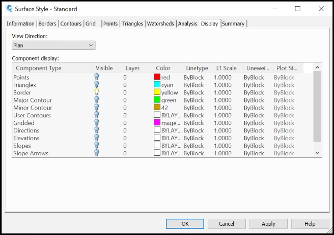
- To be able to view the design as individual triangles, we’ll have to edit the surface style. Right-click and select Edit Surface Style. In the dialog box, navigate to the Display tab. Disable all the surface style attributes by clicking on the lightbulb icons, except for Triangles.
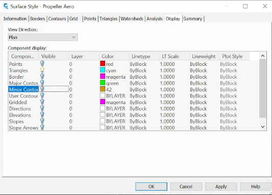
This will make it so that the model is only displayed as triangles in model space.
- Select the TIN surface and enter the command “explode”. This will convert the TIN surface to a block reference. Type “explode” once more to convert the block reference to individual 3D faces.
- To export the DXF, click Save As and select Other Formats. In the dialog box, set the Files of Type to AutoCAD 2018 DXF (*.dxf) and choose your desired folder location.
- Before exporting the design, we want to make sure no extra objects are being included in the file. Click the Tools dropdown and select Options. In the Saveas Options dialog box, select the DXF Options tab and check the Select Objects box. Click OK and then save the design.
- Back in model space, your cursor will change to a box with the text “Select Objects.” You can now create a box around your design which will specify that the design triangles are the only objects that should get exported.
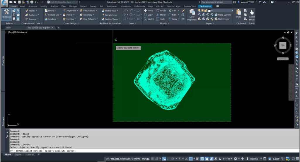
- Click Enter to export the DXF.
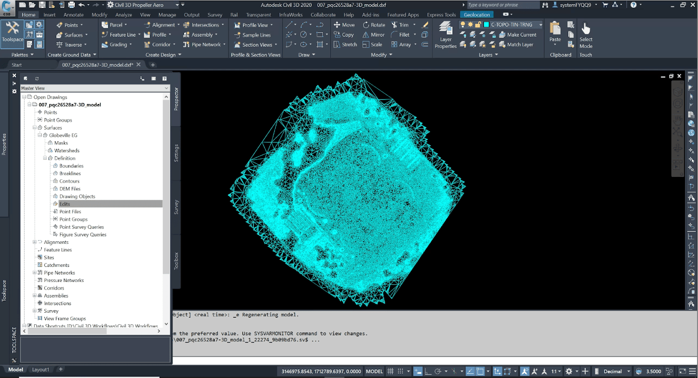
3. How to create a TIN Surface from a DXF export
Some drone software is capable of visualizing your site as a 3D model, which you can export as a TIN surface to use in Civil 3D. In the reverse of the previous workflow, doing this will require you to convert a DXF file into a TIN surface Civil 3D will recognize.
- Open the DXF 3D model file in Civil 3D. This DXF file contains 3D faces which will be used to generate the TIN surface. Once the DXF is opened, make sure you are in model space, with the 3D faces in view. If you do not see the 3D faces, double-click the mouse scroll wheel or enter the command “ze” to bring them into view.
(The 3D faces will automatically be set to layer 0. It’s recommended, but not mandatory, to create a new layer and assign the 3D faces to that.)
- On the Home tab, click the Surfaces dropdown, then click Create Surface. In the dialog box, name the TIN surface and assign it to the appropriate layer.
- In your Toolspace, open the Prospector tab. In the accordion menu, navigate to Surfaces > you surface > Definition.
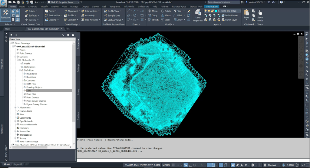
- Right-click Drawing Objects and select Add from the dropdown. In the dialog box, change the Object type to 3D faces. Check the Maintain edges from objects box. Click OK.
- Click and drag your mouse to create a selection box around your design. Hit enter on your keyboard. This will create the TIN surface.
- Set your layer to the one your new TIN surface is assigned to. Enter the command “layoff”. Click on any 3D face on your TIN to turn off the layer it’s assigned to. Since these 3D faces have been added to the TIN surface definition, it is okay to turn them off or freeze them. Don’t delete them, as they are part of the surface definition.
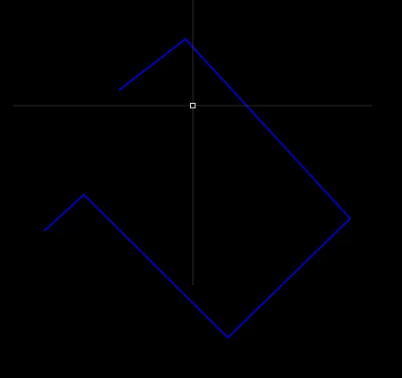
- Your TIN Surface will be rendered in the style selected at the beginning of this workflow in the Create Surface dialog box. You might see only the border.
If that’s the case, right-click the surface, and select Edit Surface Style. In the dialog box, navigate to the Display tab. All the attributes associated with the TIN surface can be toggled on and off, including major and minor contours, triangles, and the border.
- Save the DXF as a new DWG.
4. How to simplify a TIN surface
Whichever drone surveying platform you work with, there will be a limit on the size of the TIN surface you can upload. The size of a TIN is measured in the number of triangles, or 3D faces. , This workflow will outline how to reduce the number of triangles in a TIN surface so that you can upload it to your drone data software of choice as a DXF.
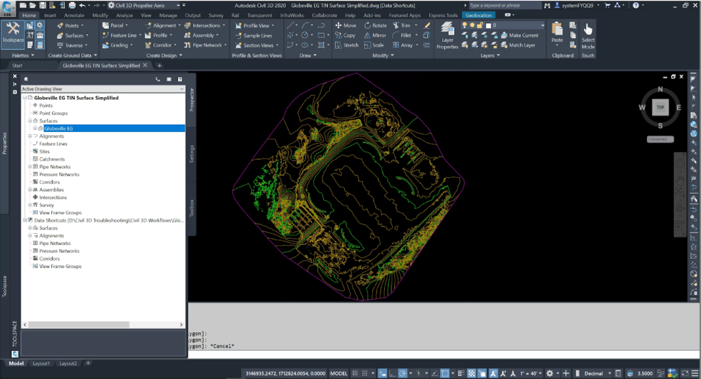
- Open the existing DWG file containing the TIN surface. The drawing should already be georeferenced by the customer in the proper coordinate system and set to the correct units (US Survey Feet).
- Locate the TIN Surface under the Prospector tab of your Toolspace:
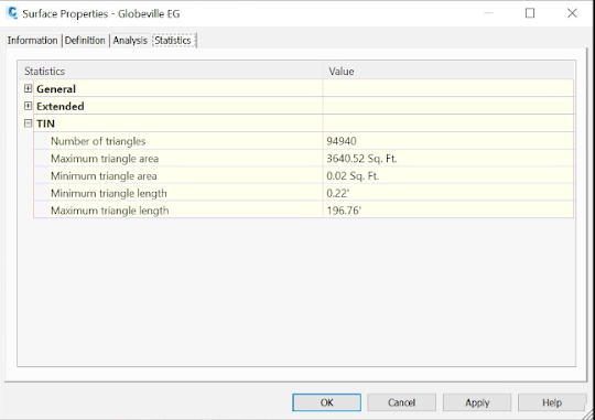
Right-click on the surface name and select Surface Properties.
In the Statistics tab of the dialog box, expand the TIN category to see the number of triangles (3D faces) the TIN surface contains. If the number is above the acceptable triangle limit for your drone survey software of choice, continue with this workflow.
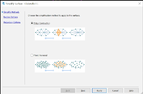
- Back in the Prospector tab of your Toolspace, navigate to Surfaces > [the name of your surface] > Definition > Edits. Right-click Edits and select Simplify Surface.
In the dialogue box, select Edge Contraction and click Next.
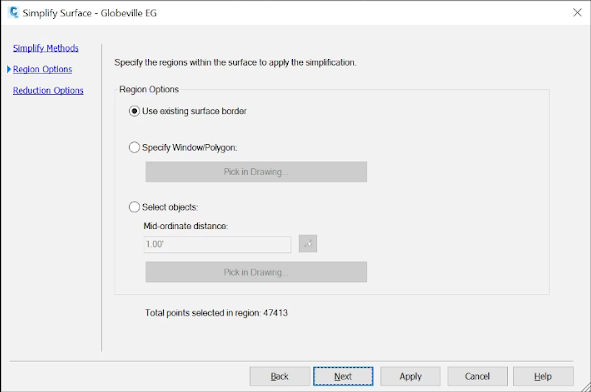
In the second dialog box, confirm that your region is set to Use existing surface border and click Next.
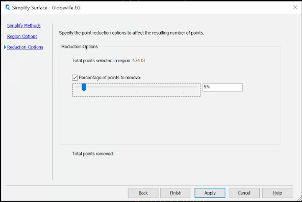
In the final dialog box, you’ll specify what percentage of triangles you need to remove from the TIN surface to get to an acceptable amount for your drone survey software. (Make sure to check the box next to Percentage of points to remove.)
Enter a percent to remove and the dialog box will calculate how many triangles the TIN will have left. Hit Apply once you’ve determined the correct percent to remove.
(If the number of triangles are not reduced enough, go to the Prospector tab of your Toolspace and navigate to Surfaces > [the name of your surface] > Definition > Edits A list of edits will appear below the Toolspace palette. Delete the Simplify Surface edit and repeat Step 3.
- When you are satisfied with the number of triangles, export your TIN surface as a DXF
NOTE: Surfaces created or modified by adding drawing objects like feature lines, contours, points or 3D faces will need to be exported as a LandXML file and imported back into a clean drawing in Civil 3D. TIN surfaces with drawing objects attached are not able to be simplified.
You can easily export your surface to an XML file by navigating to the Prospector tab in the Toolspace, expanding the surfaces category, right-clicking on the surface name and selecting Export LandXML. To import an XML file into Civil 3D, enter the command “XMLIN” and navigate to the folder containing the XML file.
5. How to create a 3D pipe network DXF
Utility strikes are inconvenient, costly mistakes that every contractor tries to avoid. The easiest way to do this is to maintain visibility on the utility line work beneath the surface on your site. Here, we’ll walk you through creating a pipe network DXF file in Civil 3D, which can be used alongside your survey data.
- Open the drawing that contains the pipe network. If the pipe network is in an XML file, type the command “xmlin” in model space to open it.
- Civil 3D cannot convert pipes and connecting structures—such as manholes—at the same time. Save the pipe network as two separate drawings. We will combine the pipes with the structures drawings later in the workflow.
- In your first drawing, right-click a structure and choose Select Similar to select all the structures. Hit delete on your keyboard.
- With all the structures removed from the drawing, we can begin modifying the pipe styles. Right-click on any pipe and select Edit Pipe Style. In the dialog box, navigate to the Display tab. Turn off all Component Types except for Pipe Solid, which is the 3D portion of the pipe.

- Click and drag your mouse to create a selection box around all your pipes. Type the command “explode” to convert the pipes to block references. Do the same thing again to convert the block references to 3D solids.
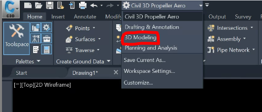
- In the workspace selection dropdown at the top of your screen, switch to 3D Modeling. The 3D Modeling workspace is where we will perform the conversion of the pipe 3D solids to 3D faces.
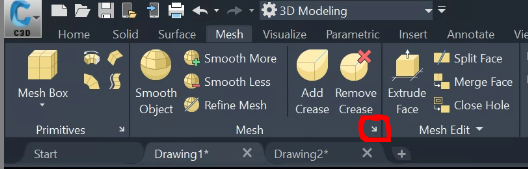
- Create a selection box around all the pipe 3D solids in your drawing. Navigate to the Mesh subsection of the Mesh tab. (Yes, they are both named that.) Click the small arrow in the bottom-right.
In the dialog box, set the Mesh type to Triangle. You can change the Mesh distance to adjust the density of the mesh, if desired.
- For your second drawing, repeat steps 3-7, this time deleting the pipes and leaving the structures.
- Now we will combine the two drawings. In the structures drawing, hold down ctrl + shift + c to copy all the structure mesh objects. When you do, a Specify base point box will appear. Type 0 into the box, press tab on your keyboard, and type 0 into the second box that appears. Hit enter to copy the structure mesh objects at a basepoint of 0,0.
- Switch to the drawing with the pipe mesh objects and hold down ctrl + v to paste the structures objects. Repeat the previous step when the Specify base point box appears again.
- The structure and pipe mesh objects are now in the same drawing. Create a selection box around all the objects. Enter the command “explode” to convert all mesh objects to 3D faces.
- Export the drawing to a DXF by entering the command “dxfout”. Save the DXF to your desired folder location.
Now that you understand how drone surveying and Civil 3D can be used together to improve construction workflows, take a look at how drone data software works with your surface design files:
Beyond CAD: Who else in your organization benefits from drone surveys?
Civil 3D design and documentation is only one of many use cases for drones in construction. As drone surveying continues to become more commonplace on construction and civil engineering projects, the accessibility and usefulness of drone data has improved along with it.
User-friendly, interactive drone surveying platforms are being used by personnel at all levels—from GIS specialists and construction surveyors to on-site managers—to map, measure, and uncover critical insights about their worksites.