To survey a site with significant elevation change you will need to fly two different missions—one from the highest point and one from the lowest. You will also need to have ground control at each change in elevation. The two flyovers should then we processed into a single dataset.
This is where we’re going if you want to jump ahead:
Similar to how everyone has their own way of interpreting accuracy, there’s subjectivity around what qualifies as a significant elevation change and what does not.
Regardless of how you interpret the word significant, the steps you follow to survey a worksite with elevation changes stay the same.
Here we’ll talk through the workflow modifications that’ll get you the most accurate 3D model of a worksite with significant elevation changes.
There’s three things to think about:
- Flight planning
- Ground control placement
- Processing
Just as a forewarning, this article gets fairly technical. You’ll need to understand the basics of ground control, photogrammetry, and PPK to get the most out of it. If you don’t know what these things are, here’s some preliminary reading to do:
Who’s dealing with elevation changes?
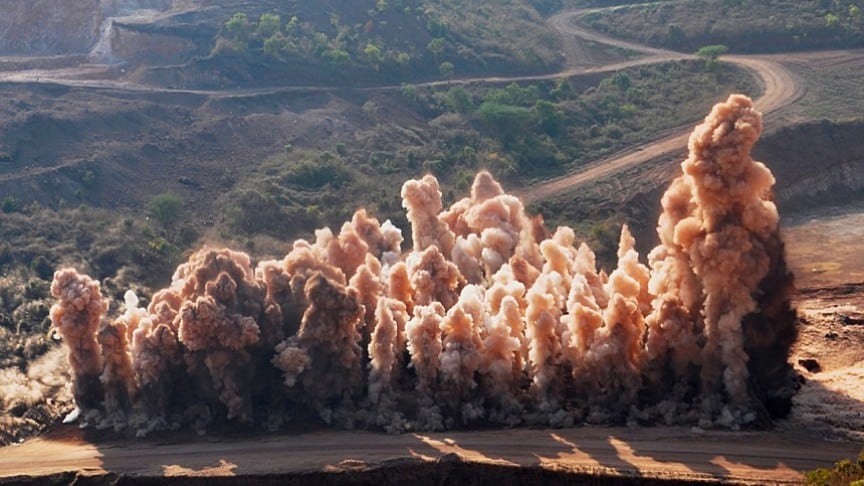
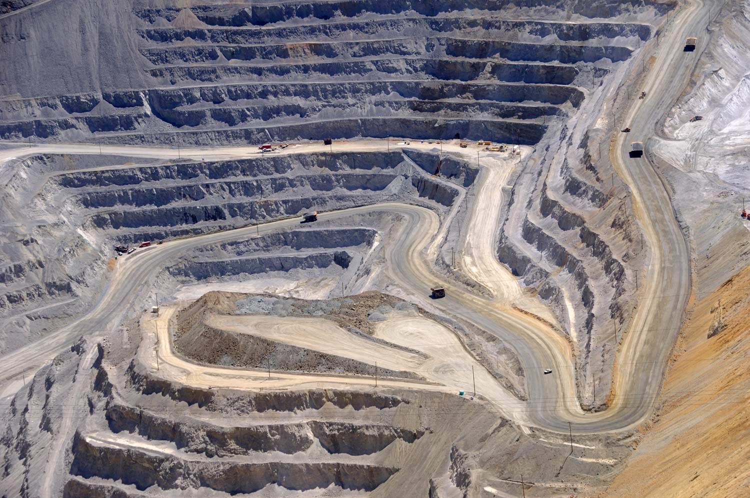
For mines and quarries, capturing elevation is everything—you’re digging down deep, excavating earth, and relying on survey data to guide your next blast. Sometimes the pit you’re working from is 400ft deep, but you still need visuals on how extraction is progressing.
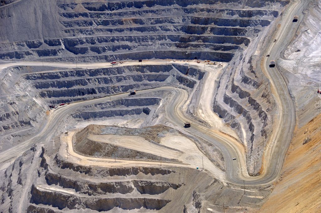
Large vertical climbs make surveying challenging (if not sometimes impossible). Having your surveyor descend a football field below the earth to shoot points with a base and rover isn’t just time consuming, it’s dangerous.
Because of the cost and risk of traditional surveying, pit and underground mines often lean on outdated datasets to guide decision making.
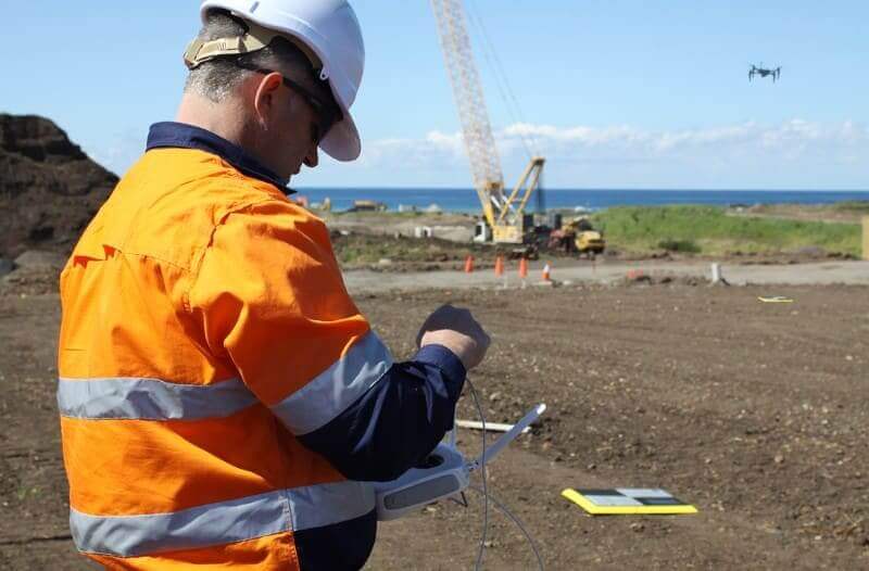
When drones emerged, the rules changed. Automated flyovers have increased site safety, while reducing guesswork—a win-win.
The catch? Even with a drone, significant elevation changes are still more difficult to capture than flat terrain.
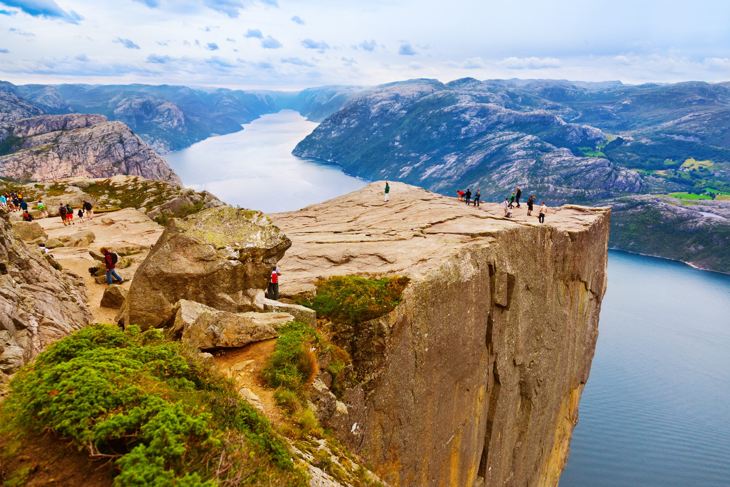
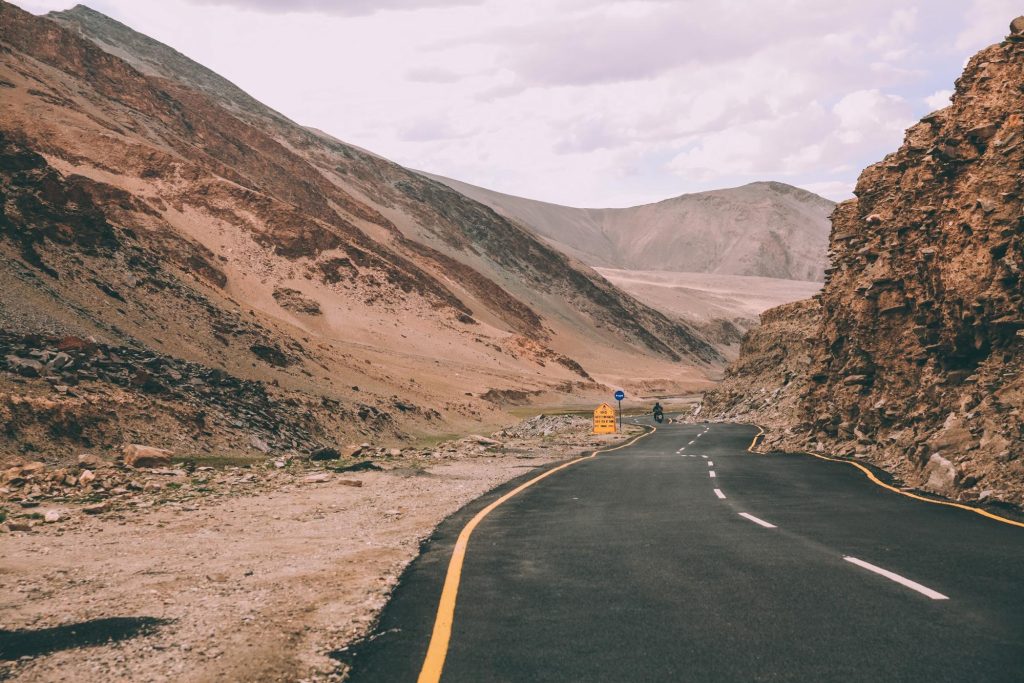
Pit mines aren’t the only sites where physical barriers hinder data collection. This can happen on any site with unruly terrain. Maybe you’re working a road job in a mountain area, and getting to the highest point of the corridor isn’t possible because the land’s undeveloped.
If you’re planning to fly a site where you’re gaining or losing elevation, you’ll have to be more strategic with your flight planning, ground control placement, and data processing.
Rethinking your flight plan (why two datasets is better than one)
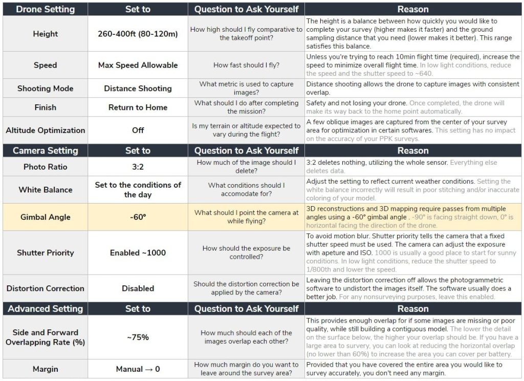
Three things to think about: GSD, doubling up on flyovers, and camera angle. First, let’s talk about GSD.
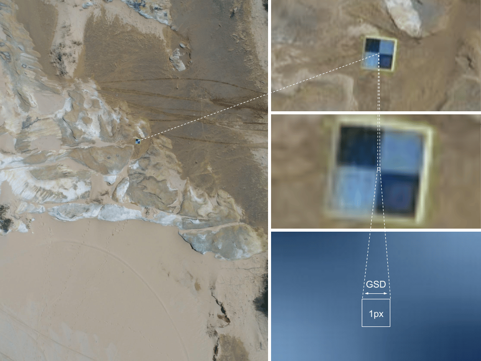
One of the most important variables in the drone survey is ground sampling distance (GSD), or the distance between the center points of two neighboring pixels.
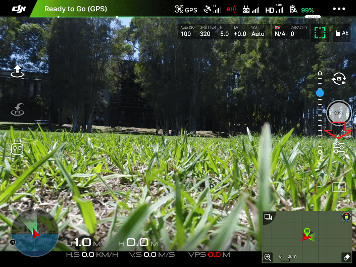
Below we can see an AeroPoint that was captured 30m (~100ft) above the ground with a DJI Phantom 4 Pro or Phantom 4 RTK. If we zoom all the way in, we can see individual pixels that make up the image. In this example, each of these pixel represents a 0.82cm (~0.32in) square in the real world. This is the GSD.
Drones are programmed to fly at a consistent height. Say you’re flying at an altitude of 300ft. If you take off from the lowest point, which is 200ft below ground-level, you’ll eventually be flying very low to the ground as the elevation increases. If you take off from the highest point, you’ll eventually be so high above the lowest point that the GSD will be too large to capture anything accurately.
(Note: If you need to calculate GSD, we have a free calculator for that)
Since your drone isn’t intuitively increasing or decreasing it’s height based on the elevation below, you’ll wind up with a disjointed dataset that has no consistent GSD. This brings us to doubling up on your flyover.
One of the ways to mitigate the inconsistencies caused by elevation change is by flying the same site at two different heights. What you wind up with is two flyovers (two different perspectives). With a more robust data pool, you can build a more detailed 3D model.
Okay, so you’re flying the site twice, but do you fly the same flight path both times? This depends on what you’re trying to accomplish.
Typically the camera gimbal on the drone is facing directly downward, and it’s capturing a pyramid of points. You would think the images it captures would be flat and one-dimensional, but this isn’t the case.
But, we can build 3D models from 2D photos by knowing the distance between photos and having sufficient overlap between images. The way those images overlap largely depends on the planning method you choose.
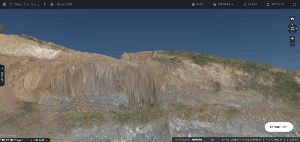
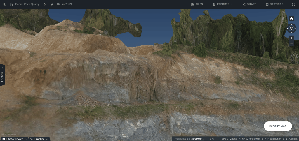
If you fly the same flight pattern twice on the “2D Photogrammetry” setting, you’d still come out with a 3D model and achieve the level of accuracy you want (1/10ft), but your vertical sides would have a melted ice cream look. You can see this in the screenshot below.
When requested, Propeller has the ability to turn on the option for customers to upload a dataset with Vertical Face Imagery in the backend. The reason it’s not always turned on is because vertices aren’t necessary for a lot of our customers logging in to measure stockpiles and other material movement.
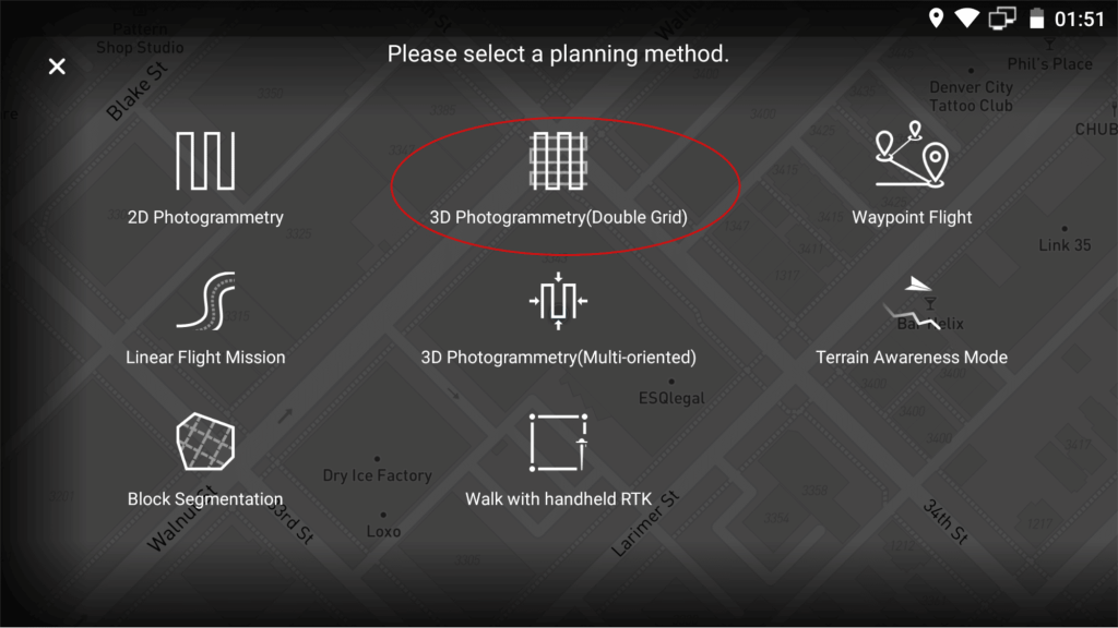
The way you bring vertices into focus is by planning a mission using the “3D Photogrammetry (Double Grid)” setting and capturing oblique imagery. Oblique imagery is collected by switching up the gimbal angle. The “Double Grid” setting flys with the gimbal at -60° the whole time in an overlapped grid. With the gimbal angled, you’ll have a more diverse dataset that we can build vertical faces from.
And rather than flying the same flight pattern twice, you’d fly your highest elevation north to south at a greater height and your lowest elevation east to west. This grid-like flight pattern, in combination with the gimbal angle, fills in those melted vertices with high-res imagery.
With vertical imagery, here’s what the quarry incline in the screenshot above ends up looking like. No more melted ice cream.
One thing to keep in mind here is time. Inevitably, missions planned with vertical face imagery in mind are going to take longer to fly and to process. However, doubling up on flights to get consistent GSD won’t take any longer than usual (but, we’ll get to the processing later on).
To sum up this section—fly two 2D photogrammetry missions at different elevations to get consistent GSD and fly a 3D mission at two different elevations to get vertical face imagery.
Getting control over your ground control points
With the following, we’re assuming you already have a handle on ground control—why it exists, why it’s important, and how to establish permanent ground control points (GCPs).
Just like how we fly at different heights to get the most consistent results, we need to place our GCPs at different heights. On sites with benches or significant elevation change, you want to have ground control on the lowest point, the highest point, and the middle ground. This gives you three stable points to tie your model to.
If you’re using the Propeller PPK workflow, you’ll need three AeroPoints. For non-PPK users, your GCP distribution should look something like the mock-up below.
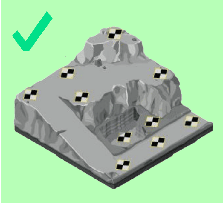
As you can see, there’s a set of GCPs at every elevation and they’re evenly distributed. With PPK, you’d have one at the very lowest elevation, one mid-level, and one at the highest point.
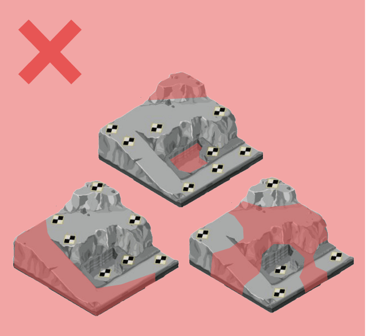
What you don’t want is an elevation that goes unrepresented. In the diagram above, the red sections do not have any GCPs, even though they represent changes in elevation. This would result in inconsistent survey data.
The power of Propeller processing—how we combine datasets into one interactive visualization
Yes, surveying the same site twice takes more time, but the automated aspect of drones makes it relatively painless. Processing and combining your two flyovers to create one complete, consistent dataset can be the hardest part of the elevation survey workflow.
There’s good news though: processing elevation surveys doesn’t have to be hard. That’s the beauty of processing with Propeller—we do all the heavy lifting for you.
You can fly the same site twice, from different elevations, and the Propeller Platform will select the right photos from the two different flights and piece together the most accurate model possible.
Wondering about how the processing works? Here’s everything you need to know.
Once you’ve mitigated elevation changes with repeat flyovers, let us combine the datasets, and uploaded the combined dataset to the Propeller Platform, your 3D model will be ready for analysis. Let’s explore some of the awesome ways you can engage with your elevation data.
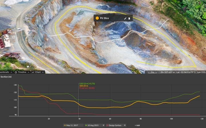
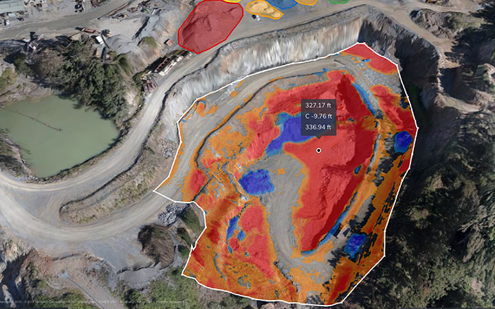
Track progress against design
Upload design surfaces to visually track progress against your 3D site survey and see how far you’ve got to go. Compare one survey to another to see changes over time. Spot nonconformance issues before they become expensive.
Calculate volumes
Forget sending someone out to walk a pile. Measure your volumes in seconds on the Propeller Platform. Shave hours off your workflow and get better estimates on your inventory. Make huge write-offs a thing of the past.
Save time and reduce risk
Fly as often as you need. Complete site surveys in hours instead of days. Get your results in 24 hours. Use Propeller to plan blasting and extraction and monitor haul roads with easy-to-use measurement tools and 3D visuals.
Long story short: surveying worksites with large elevation differences is totally doable, and much easier to do more frequently with UAV tech. Sure, it’s going to take longer, but by following the steps above, you’ll end up with a high-res, highly measurable 3D model with the vertical imagery you’re looking for.