Ground control is the go-to option for turning drone data into highly accurate, survey-grade models. While we have already covered the benefits of ground control in one of our previous posts, there are still a few things you should know about marking and recording ground control points (GCPs) to make sure your data is processed accurately the first time.
How do I measure my ground control?
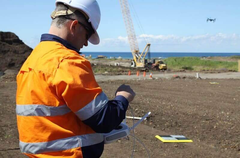
The most common method for recording ground control measurements is via an RTK-enabled GPS rover using correction data streamed from a nearby reference station. In some cases, ground control can also include known survey marks which can have a marker placed on top of them to be found in your aerial imagery.
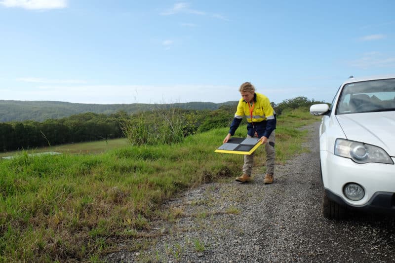
Alternatively, Propeller’s AeroPoints achieve survey-grade accuracy without the time consuming task of manually measuring and marking chosen locations.
What should my markers look like?
Most markers meet two simple criteria:
1. High contrast design to be easily distinguished from surrounding terrain.
2. Clear geometry indicating the measured centre of the marker.
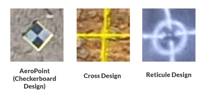
With this in mind, the most commonly used marker designs are either a crosshair or checkerboard design.
If you are planning to use ground control but haven’t settled on a design yet, the markers below are a good start:
Where should I place my markers?
Markers should be placed around the outer corners of a site with the remainder distributed throughout the center of the site.
A rule of thumb is that a survey of any size requires a minimum of five GCPs to be adequately covered with around 10 per 120 hectares for larger sites.
When picking locations to place your ground control, always pay mind to what the chosen area would look like from your drone. A GCP is useless if it is obscured by trees, buildings or fences in the final imagery.
Finally, GCPs should always be measured at ground level to minimize the risk of elevation error in the terrain of the final 3D model.
What if I don’t have marker mats or can’t mark the site with paint?
Occasionally the nature of a site prevents the use of conventional markers for ground control, in this case it’s best to examine the site prior to flying and find locations that meet the two criteria mentioned above. Some examples of what make good markers are included below:
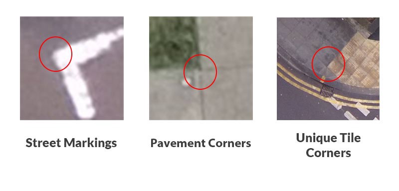
In most cases using preexisting features on the ground as GCP markers should be avoided unless absolutely necessary and that features should be chosen at ground level (i.e. the top of a pole is not a good marker for ground control).
If you do use these kinds of features as a basis for your ground control, it is critical that a few annotated examples are provided from the aerial imagery gathered during your survey to highlight exactly which feature was used as the location for each GCP.
Best practices for capturing your markers
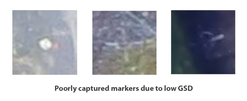
The accuracy of outputs generated by photogrammetry are primarily limited by the ground sample distance (GSD) of the provided imagery and the same is true for aerial surveys using ground control.
If the GSD of aerial imagery is 5cm and the painted lines defining one of your markers are only 3cm wide then there is a fair chance your GCP will be unrecognizable in the final imagery and unable to be used. Making sure you choose a flight altitude to meet a GSD where your markers are clearly defined is crucial otherwise they are likely to be impossible to recognize during processing.
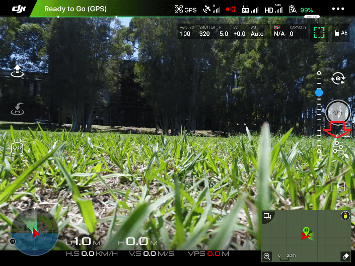
As obvious as it might sound, another consideration is to make sure you fly over your markers after you’ve marked them. An unfortunately common mishap is for pilots and surveyors to plan out ground control only to have the flight path fall short of capturing the marker.
In some cases, it may be best to plan a flight path that covers an area slightly larger than your intended survey area to ensure you have captured all markers in multiple images.
What information do I need to provide to have my survey processed with GCPs?
When you’re finally ready for your GCPs to be processed we need four things to proceed:
1. Points in a .csv formatted in a “marker label,x,y z” format.
2. Marker coordinates provided as grid coordinates instead of ground.
3. EPSG code of the projection in which these coordinates are recorded (for information of the EPSG code for your local region see www.epsg.io).
4. If preexisting features are used instead of markers, an annotated list of images in which GCPs are present.